Locomotive Seats Australia
Ph: 61 7 3274 1231 Fax: 61 7 3274 1320
email: sales@locoseatsoz.com
53 Magnesium Drive, Crestmead QLD 4132
BRISBANE AUSTRALIA
Locomotive Seats Australia
Ph: 61 7 3274 1231 Fax: 61 7 3274 1320
email: sales@locoseatsoz.com
53 Magnesium Drive, Crestmead QLD 4132
BRISBANE AUSTRALIA
FEDERAL MOTOR VEHICLES SAFETY STANDARDS
FMVSS302
| S571.302 STANDARD No 302 – FLAMMABILITY OF INTERIOR MATERIALS | |||
| S1 | SCOPE – This standard specifies burn resistance requirements for materials used in the occupant compartments of motor vehicles. | ||
| S2 | PURPOSE – The purpose of this standard is to reduce the deaths and injuries to motor vehicle occupants caused by vehicle fires, especially those originating in the interior of the vehicle from sources such as matches or cigarettes. | ||
| S3 | APPLICATION – This standard applies to passenger cars, multipurpose passenger vehicles, trucks and buses. | ||
| S3a | DEFINITIONS – Occupant compartment air space means the space within the occupant compartment that normally contains refreshable air. | ||
| S4 | REQUIREMENTS | ||
| S4.1 | The portions described in S4.2 of the following components of vehicle occupant compartments shall meet the requirements of S4.3: Seat cushions, seat backs, seat belts, headlining, convertible tops, arm rest, all trim panels including door, front, rear, and side panels, compartment shelves, head restraints, floor coverings, sun visors, curtains, shades, wheel housing covers, engine compartment covers, mattress covers and any other interior materials, including padding and crash deployed elements, that are designed to absorb energy on contact by occupants in the event of a crash. | ||
| S4.1.1 | [Reserved] | ||
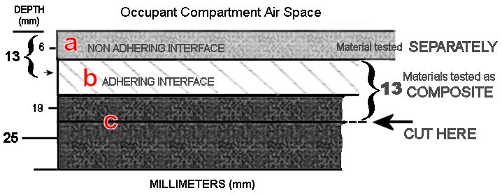
| S4.2 | Any portion of a single or composite material, which is within 13mm of the occupant compartment air space, shall meet the requirements of S4.3. | ||
| S4.2.1 | Any material that does not adhere to other material(s) at every point of contact shall meet the requirements of S4.3 when tested as a composite with the other material(s). | ||
 OCCUPANT COMPARTMENT AIR SPACE All dimensions in Millimeters (mm) |
|||
| S4.3 | <Material “A” has a non-adhering interface with material “B” and is tested separately. Part of material “B” is within 13mm of the occupant compartment air space and materials “B” and “C” adhere at every point of contact; therefore, “B” and “C” are tested as a composite. The cut is in material “C” as shown, to make a specimen 13mm thick. | ||
| S4.3a | When tested in accordance with S5, material described in S4.1 and S4.2 shall not burn, nor transmit a flame front across its surface, at a rate of more than 102mm per minute. The requirement concerning transmission of a flame front shall not apply to a surface created by cutting a test specimen for purposes of testing pursuant to S5. | ||
| S4.3b | If a material stops burning before it has burned for 60 seconds from the start of timing, and has not burned more than 51mm from the point where the timing was started, it shall be considered to meet the burn-rate requirements of S4.3a. | ||
| S5.1 | CONDITIONS | ||
| S5.1.1 | The test is conducted in a metal cabinet for protecting the test specimens from drafts. The interior of the cabinet is 381mm long, 203mm deep and 356mm high. It has a glass observation window in the front, a closable opening to permit insertion of the specimen holder and a hole to accommodate tubing for a gas burner. For ventilation, it has a 13mm clearance space around the top of the cabinet, ten holes in the base of the cabinet, each hole 19mm in diameter and legs to elevate the bottom of the cabinet by 10mm, all located as shown in Figure 1.< | ||
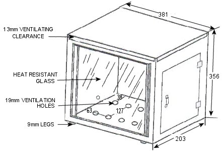 FIGURE 1 ALL MEASUREMENTS IN MILLIMETRES (mm) |
|||
| S5.1.2 | Prior to testing, each specimen is conditioned for 24 hours at a temperature of 21°C and a relative humidity of 50% and the test is conducted under those ambient conditions. | ||
| S5.1.3 | The test specimen is inserted between two matching U-shaped frames of metal stock 25mm wide and 10mm high. The interior dimensions of the U-shaped frames are 51mm wide by 380mm long. A specimen that softens and bends at the flaming end so as to cause erratic burning is kept horizontal by supports consisting of thin, heat resistant wires, spanning the width of the U-shaped frame under the specimen at 25mm intervals. A device that may be used for supporting this type of material is an additional U-shaped frame, wider than the U-shaped frame containing the specimen, spanned by 10-mil wires of heat resistant composition at 25mm intervals, inserted over the bottom U-shaped frame. | ||
| S5.1.4 | A Bunsen burner with a tube of 10mm inside diameter is used. The gas-adjusting valve is set to provide a flame, with the tube vertical, of 38mm in height. The air inlet to the burner is closed. | ||
| S5.1.5 | The gas supplied to the burner has a flame temperature equivalent to that of natural gas.> | ||
| S5.2 | PREPARATIONS | ||
| S5.2.1 | <Each specimen of material to be tested shall be a rectangle 102mm wide by 356mm long, wherever possible. The thickness of the specimen is that of the single or composite material used in the vehicle, except that if the materials thickness exceeds 13mm, the specimen is cut down to the thickness measured from the surface of the specimen closest the occupant compartment air space. Where it is not possible to obtain a flat specimen because of surface curvature, the specimen is cut to not more than 13mm in thickness at any point. The maximum available length or width of a specimen is used where either dimension is less than 356mm or 102mm, respectively, unless surrogate testing is required under S4.1.1. | ||
| S5.2.2 | The specimen is produced by cutting the material in the direction that provides the most adverse test results. The specimen is oriented so that the surface closest to the occupant compartment air space faces downward on the test frame. | ||
| S5.2.3 | Material with a napped or tufted surface is placed on a flat surface and combed twice against the nap with a comb having seven to eight smooth, rounded teeth per 25mm. | ||
| S5.3 | PROCEDURE | ||
| (a) | Mount the specimen so that both sides and one end are held by the U-shaped frame and one end is even with the open end of the frame. Where the maximum available width of a specimen is not more than 51mm, so that the sides of the specimen cannot be held in the U-shaped frame, place the specimen in position on wire supports as described in S5.1.3, with one end held by the closed end of the U-shaped frame. | ||
| (b) | Place the mounted specimen in a horizontal position, in the centre of the cabinet. | ||
| (c) | With the flame adjusted according to S5.1.4, position the Bunsen burner and specimen so that the centre of the burner tip is 19mm below the centre of the bottom edge of the open end of the specimen. | ||
| (d) | Expose the specimen to the flame for 15 seconds. | ||
| (e) | Begin timing (without reference to the period of application of the burner flame) when the flame from the burning specimen reaches a point 38mm from the open end of the specimen. | ||
| (f) | Measure the time that it takes the flame to progress to a point 38mm from the clamped end of the specimen. If the flame does not reach the specified end point, time its progress to the point where flaming stops. | ||
| (g) | Calculate the burn rate from the formula: B = 60 x (D/T)
B = Burn rate in millimeters per minute D = Length the flame travels in millimeters T = Time in seconds for the flame to travel D millimeters |
||
(36 FR 22902, Dec 2 1971, as amended at 40 FR 14319, Mar 31 1975: 40 FR 42747 Sept 16 1975: 40 FR 56667 Dec 4 1975: 63 FR 28954, 28958 May 27 1998: 63 FR 51008 Sept 24 1998)